Saturday, 14 December 2019

Timer

Date of completion: 2018-19

Design

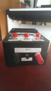
Having bought a small solar powered cascade for the pond in 2018, I soon discovered that it had a very limited range of settings for the length of time for which it could be switched on each day. So I bought some more solar panels to boost the charging rate and then set about designing my own daily timer for it. The timer is based around a Microchip PIC16F628 (programmed in assembler) with an LCD display and three push buttons to set current time, time for switch-on and time for switch-off. The pump current is switched on and off by an n-MOSFET. There is also a reset button, which is useful to recover from glitches and also to switch the pump off permanently without unplugging everything. In addition it has a means of overriding the current settings, so that the cascade can be switched on during an off-period, and vice versa. The display switches itself off via a p-MOSFET after a certain time (about 2 minutes) during an off-period in order to save the battery charge (the display current, however, is fairly small compared to that of the pond pump, so it makes sense to leave the display on during those times.)
Later I added a comparator to ensure the whole thing switches off if the battery voltage falls below 4V (the cascade controller has a 6V SLA cell.) Later still I added a solid state relay, so that the timer could be used for other circuits, e.g. Christmas lights.

Photos


Circuit Diagram

Tiny CAD (.dsn) files: Timer


Source code and other files

Timer.asm - All files (zipped)

Sunday, 24 February 2019

PP3 Battery Saver

Date of completion: 2014

This very simple circuit is yet another I constructed for school, where some devices were "eating" PP3 batteries very rapidly, especially because the devices were not always turned off at the end of a lesson (grrr!) I swiped the design (OK, "adapted it") from a website somewhere! The circuit solves the problem by having a push switch providing 10 minutes of power, after which the button needs to be re-pressed or the device switches off. Switch-off reduces the current consumption to less than 1 microamp, which is negligible for a PP3 battery.

Design

Pressing the push-switch charges up the large capacitor and switches on the n-channel MOSFET (2N7000), which has a very low on-resistance. Gradually the capacitor discharges through the 2.2 Mohm resistor, until the gate voltage is low enough that the MOSFET switches off suddenly.

Circuit Diagram

Tiny CAD (.dsn) files: PP3 Battery Saver


Mini Oscilloscope

Date of completion: 2010-2015

This was my first successful attempt (earlier attempts might be considered part of a steep learning curve!) to construct a small, portable oscilloscope. It also incorporates the extra functions of a stopclock and a voltmeter. For a later, more sophisticated design of portable oscilloscope, see "TFT Oscilloscope". Although the resolution of the graphics display is low and the fastest timebase is relatively slow (it is, however, OK for audio frequencies), the big advantage of this design is its very low battery consumption, helped particularly by having a full, timed power-down mode.

Photos


Design

The input stage of MiniOsc is an instrumentation op amp, giving it a properly differential input with a high input impedance of around 2 MOhms. TTL analogue switches (SN74HC4066) combined with four standard op amps (MC33204) are used to change between DC and AC amplification and for gain control. The ADC is an 8-bit TLC0820. The microprocessor used is a 40-pin PIC18F4550 driven by a 20MHz quartz crystal and it has a reference voltage provided by an LM285 to correct for variations in the power supply. The power supply is either four AA cells or an external power supply stepped down by an LM317 voltage regulator. As the battery is not connected via a regulator, full power-down can be achieved when the p-channel MOSFET (ZVP2106A) is switched off.
There are two LCD displays, one graphic and the other 16-character, both of which are powered via the MOSFET. The PIC, of course, has its own power-down function, reducing the total current drawn to less than 1 microamp when the MiniOsc is not being used. It can easily returned to its state before power-down (after a timeout, which occurs after a few minutes of no button-presses), using the "wake" button.
Programming was performed in Assembler using a number of different linked routines (listed below.) With a 20MHz crystal it was possible to program accurate oscilloscope timing and triggering, even for several  tens of kSamples per second. This did, however, involve some very careful counting of program cycles!

Circuit Diagram

Tiny CAD (.dsn) files: MiniOsc3


Source code and other files

MiniOsc.asm  MiniOsc.inc  Control.asm  GLCD.asm  LCD.asm  Menu.asm  Sample.asm  Stopclock.asm  Volt.asm   All files (.zip)

Microwave Detector

Date completed: 2014

This is another device constructed for school Physics teaching. It demonstrates well that microwaves are emitted (and a few escape) from a microwave oven and also from a mobile phone by sounding a buzzer and lighting a red LED (once the variable resistor is adjusted just above the continuous background noise.) You even hear the characteristic rhythm of the mobile phone connection: tum-tum-tee-tum!

Photo and School instructions

Design

I can't tell you much about how this works, except that it has an oscillator made from an op amp (half of a 741) and a capacitor, which can be made unstable by the adjustment of the variable resistor. This somehow then picks up any radio noise nearby (acting as a weak aerial, I suppose) and the resulting oscillations are then amplified (and saturated) by another op amp with a very high gain (no feedback.) I must have found the circuit or a similar one on the internet somewhere!

Circuit Diagrams

Tiny CAD (.dsn) file: Microwave Detector


Saturday, 23 February 2019

Speed of Light Apparatus

Date of completion: 2015

When teaching either the topic of Total Internal Reflection (of light) or Communications to GCSE students I always felt that it would be much better to see optical fibres in use than simply to talk about them. The device here measures the time for an optical signal to travel along an optical fibre, and from this a fairly accurate value for the speed of light in a glass fibre can easily be calculated.  This is clearly useful when teaching about refractive index. I bought a 100 metre reel of double optical fibre from Ebay (ensuring it had the correct optical connectors) and then another much shorter length of optical fibre (blue in the picture) to return the output signal back along the input fibre (making a total length of just over 200 metres.) Given that the refractive index of glass is about 3/2 and so the speed of light in it is about 200,000,000 m/s, this gives a time delay of roughly 200 / 2 x 10^8 seconds or 1 microsecond. This is just measurable using a 50 MHz oscillator and its accuracy is greatly improved by averaging over multiple transits.
Inevitably there a delay due to electronics response times (about 2 microseconds, dependent temperature), but a reset button was added to subtract this from the times displayed once the unit had warmed up (about 10 minutes) to keep the demonstration simple for GCSE students!

Photos and School Instructions


Design

The hardest part of the project was finding a cheap optical transceiver on Ebay, but it wasn't long before I spotted one buried in an old non-functioning electronics unit. It turned out to be an HFBR 5803 and a search on the internet revealed its characteristic were just fast enough to make a reliable timer. Some level shifting of input and output voltages was needed, but it became apparent that with the help of an op amp it could be connected to a resettable gate made from fast TTL NAND gates in a 74HC132. This is controlled by a PIC16F628A (my favorite!) and the output is displayed on a 16 character LCD (also my favorite!) The 5 volt-powered 50 MHz oscillator came, as ever, from Ebay, and these signals are fed through the gate to the PIC which counts them repeatedly (via its TIMER0, set up as a fast counter.)
The coding is performed in assembly language so that timings could be calculated easily and reliably (with the PIC driven by a 20 MHz quartz crystal.) Most of the coding is concerned with calculating the time correctly and displaying it on the LCD display.

Circuit Diagrams


Tiny CAD (.dsn) files: Light2

Source code and other files

Light2.asm  All files (.zip)

GPS clock

Date of completion: 2018

This GPS clock was designed to replace the radio controlled clock mentioned in another blog post. The radio signal from Cumbria was rather weak and unpredictable, whereas the GPS signal near a window is much more dependable. I enhanced it a few years later to incorporate the church alarm receiver, also mentioned in an earlier post. Not only does it indicate if the church alarm is sounding (by lighting a green LED in the side of the device - the red LED flashes every 2 seconds to indicate a signal has been received from the church tower 100 yards away), but also how close to the hour the church bell rings. (e.g. the "-9s" in the photo indicates that the bell last sounded just 9 seconds late - not bad for a church clock built in 1850!)

Photos

Design

The design of the church alarm receiver is described in an earlier post, but suffice it to say it uses a cheap 433MHz receiver and HT12D decoder with a 17.3 cm aerial (a bit bent in the photo.)
The GPS unit came from Ebay and its 3 volt RS232 signal (at a baud rate of 9600 bps) is connected to a PIC 16F628A microprocessor (running at 5V), which drives a 16 character LCD display. The PIC decodes the data from the GPS unit to display the time in hours, minutes and seconds, and the current date. Like my earlier radio-controlled clock, the PIC can continue to display the correct date and time for a short while, even if the GPS signal is lost. I have included a table to switch between Greenwich mean time and British Summer Time on the correct dates each year. I think it should currently run correctly until 2026 or so. After that I will need to program the PIC with new data for future dates!
The church bell signal is compared to the GPS time every hour between 4 minutes before and 4 minutes after the hour. This reduces possible confusion with  spurious sounds due to the church alarm sounding (a rare event) or the bell ringers practising (a regular event!)

Circuit Diagrams


Tiny CAD (.dsn) files: GPSClock

Source code and other files

GPSClockX.asm  All files (.zip)

Sunday, 17 February 2019

Organ Transceivers

Date of completion: 2019

This refers to a couple of devices (a "transmitter" and a "receiver") designed and built to facilitate communication between a church leader and an organist. These people are often situated far apart in church services, and the organist needs to be kept up to date about when to start/stop/prepare for playing. This is certainly true in Seal church, Kent, where my wife is the vicar and I sometimes attempt to play the organ!

Photos


Design

Both devices are designed around the CC1101 transceiver, which is a rather sophisticated device from Texas Instruments, but which is very cheap via Ebay. It comes with lengthy instructions and a software program to help with choosing set-up parameters. The devices also each have a PIC microprocessor. I used two quite different PICs (PIC16F1503 and PIC18F2550), as I just happened to have them available, but there are only slight differences in programming details. They are programmed very similarly using C (XC8 from Microchip, who make the PICs), although one is primarily the transmitter and the other is primarily the receiver. They respond correctly to button presses only if there is a two-way communication between them, however.

Each has an on-off switch to preserve battery life, but they are also programmed to enter standby mode after 90 minutes of inactivity. Each has a white light to indicate that it is switched on and is consuming power. I have minimized power consumption by putting the CC1101s either into SLEEP mode or WAKE-ON-RADIO mode (testing for a received signal every 1 second) between transmissions and using the SLEEP mode of the PICs whenever there is activity (waking on interrupts (a) from the CC1101, (b) from a button being pressed, or (c) from the watchdog timer to keep the white light flashing.)

When a transmitter button (red, yellow or green) is pressed a signal is sent to the receiver, which flashes the appropriate LED once and sends back a signal to the transmitter. When this signal is received the transmitter flashes its own appropriate LED once. If the original button is held down, the process repeats until the button is released. There is a HELP button on the receiver, so that the organist can attract initiate communication, if needed. When pressed the red and green LEDs on both devices flash continuously until either the HELP button is pressed again or one of the buttons on the transmitter is pressed.

When first switched on both devices flash all three coloured LEDs once. Error-trapping is enabled by resetting the CC1101 and PIC (and therefore flashing all three coloured LEDs once again) if trying to communicate when, for example, only one of the two devices is switched on. Each is powered by two AA batteries, which should last for several years before needing to be replaced (if my calculations and measurements are correct, and there are no serious bugs in the programs!)

Circuit Diagrams

Tiny CAD (.dsn) files: CC1101 Transmitter CC1101 Receiver

Source code and other files

Transmitter: CC1101T.c  CC1101.h  All files (.zip)

Receiver: CC1101R.c  CC1101R.h  All files (.zip)